Patch / Aperture Size requirements - X-Rite eXact
Maximal Aperture Size Recommendation
| Spot Mode | Scan Mode | |||
| Patch Size | Spot only* (max aperture size) | Strips < 10cm/4" (max aperture size) | Strips 10cm/4" to 75cm/30" (max aperture size) | Strips > 75cm/30" (max aperture size) |
| 2mm | 1.5mm | - | - | - |
| 3mm | 2mm | 1.5mm | - | - |
| 4mm | 2mm | 2mm | 2mm | - |
| 5mm | 4mm | 2mm | 2mm | 2mm |
| 6mm | 4mm | 4mm | 4mm | 2mm |
| 7mm | 6mm | 4mm | 4mm | 4mm |
| 8mm | 6mm | 6mm | 6mm | 4mm |
| >= 9mm | 6mm | 6mm | 6mm | 6mm |
* For spot readings, it is always recommended to use the largest aperture size possible. If the instrument is used for scanning as well, scan mode will dictate the aperture size.
Aperture Specifications
| Aperture Size | Measurement area size | Opening in target window** | Opening in scan chassis target window | Screening Range |
| 1.5mm | 1.5mm | 3.5mm | 4.0mm | 175 lines/inch or 69 lines/cm or above |
| 2mm | 2.0mm | 4.0mm | 4.5mm | 133 lines/inch or 52 lines/cm or above |
| 4mm | 4.0mm | 6.0mm | 6.5mm | 65 lines/inch or 26 lines/cm or above |
| 6mm | 6.0mm | 8.0mm | 8.5mm |
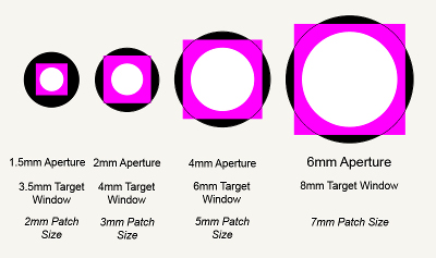
** For each eXact aperture size, the target window size is 1 mm (on radius) larger than the spot measurement area size. This 1 mm over iluumination of the measurement area is required by ISO5/4. The white area around the patch, does not influence the measurement data, but does require the operator to center the measurement sample in the target window opening.
The illustration below shows how this minimum measurement area appears in relation to the target window opening.
The black circle represents the target window opening.
The white circle represents the actual measurement area (which equals the aperture size).
The magenta square represents the minimum suggested patch size.
This can be used as a guide for operators when placing the instrument optics over patches which do not completely fill the target window opening.

